Buzzer Switch 4+3
| Buzzer Switch 4+3 | |
|---|---|
_1932_-_Plate_3_(detail).jpg) |
Origins in the Great War
The Buzzer Switch 4+3 was developed during the war as a result of the experimentation and equipment improvisation that was characteristic of the time. Many Post Office telephone and telegraph apparatus and telephone exchanges were used but were generally not robust enough for field use. In the Post Office workshops, however, were a skilled staff, a good reserve supply of standard parts of instruments, and a great eagerness to help in any way possible. G.P.O. staff made periodic visits to France to assess requirements which led to the development of the unit having seen an original improvised device at II Corps headquarters made from a spare strip for a five-line exchange and French receivers.[1] It is described as "... in spite of its bulk and the constant renewal of cords rendered necessary by the rough conditions under which it was used, was a great advance on the old plug commutator board and the endless variety of makeshift "cartridge" exchanges improvised by units. Its great merit was its almost soldier-proof solidity and its immunity to the constant immersions in candle-wax, water and Machonnochie gravy to which its dug-out life exposed it."[2]
Description
39. Telephone exchanges and buzzer switch units[3]
...
4. Buzzer switch units: --
i. When telephones D.III. are in use and a telephone system is required, buzzer switch units are used to establish telephone exchanges; there are two types of switch unit called "4+3" and "7+3." The former can accommodate seven "subscribers" but three of these are grouped on one indicating receiver. The latter can accommodate ten "subscribers," also with three of them grouped on one indicating receiver.
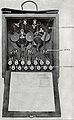
_1932_-_Figure_59.jpg)
ii. These instruments are similar in many respects. They each have one jack for each "subscriber" and one jack for the operator. One indicating receiver is supplied for each line, except for the last three, which, as mentioned above, have one receiver for the three lines. The lines and "earth" connections are led in through holes on the top of the instrument. The door at the back gives access to the terminal for the lines, earth connections, and the operator's telephone. the action of both these instruments is the same, in that buzzing calls from "subscribers" are received in the indicating receivers and the interconnection of "subscribers" is done by means of cords containing two conductors and fitted with plugs at their ends. The plugs are inserted in jacks.
5. Buzzer switch unit 4+3. (Plates III and IV). The operating instructions for this switch are contained in Sec. 81.
In this switch unit the action of inserting a plug cuts out the associated indicating receiver, no clearing signal is therefore obtained. The operator must "listen in" to ascertain whether the conversation is finished before "clearing" the connection.
Operating Instructions
81. Operating instructions, buzzer switch unit 4+3[3]
1. The operating of this unit is carried out as follows: --
i. With 3-plug cords.
The operator places the common (or centre) plug of a 3-plug cord in the "jack" marked "operator."
The "subscriber" attracts the attention of the exchange operator by calling continuously on the key of his telephone until answered. Unless a distinguishing call has been allotted to each "subscriber," the calling line must be identified by the operator. The operator can do this by placing his thumb or finger over each receiver in turn to discover which receiver is in action. The operator then inserts one of the plugs at the free end of the cord, which is already connected to the operator's "jack," in the "jack" of the calling line. if necessary he stops the "subscriber's" call by pressing the key of his exchange telephone, and answers the call by saying, ". . . exchange speaking, sir."
The "subscriber" then says, for example, ". . . (unit, officer, or code name) please." The operator repeats the name of the unit, etc., required and pauses a moment in case the "subscriber" wishes to make a correction. If the line to the required "subscriber" is disengaged, the operator will say, "one moment, please." he then removes the plug from the calling line and inserts it in the "jack" of the required "subscriber." He then calls that "subscriber" on the exchange telephone.
When the required "subscriber" answers, the operator inserts the remaining free plug of the 3-plug cord into the "jack" of the calling "subscriber," thus completing the connection, and says, "through, sir." The operator listens until the conversation begins; he then removes the common plug from the "jack" marked "operator." The common plug of another cord is then inserted in the operator's "jack" in readiness to receive the next call.
If the line to the required "subscriber" is already in use, the operator will inform the calling "subscriber" by saying, "line engaged, sir."
As it is difficult, with this switch unit, to identify a "clearing-signal" (i.e. "ring-off"), the operator must supervise calls (Sec. 80) by inserting the common plug, of the 3-plug cord in use, in the operator's "jack." If no conversation is heard he challenges by saying "finished?" three times. If there is no reply he will clear the connection by withdrawing the plugs. Any waiting call can then be put through.
ii. With 2-plug cords.
The 2 plug cord, which is sometimes issued with the 4+3 unit, consists of a cord with two plugs, one of which is of ordinary pattern (known as "plug 201"), the other being of a special pattern (known as "plug 301A"). This special plug is of larger dimensions than the ordinary pattern and is constructed to form a listening-in "jack" into which another ordinary plug can be inserted.
The operating of the unit with 2-plug cords is carried out in a manner similar to that which is described above for 3-plug cords, except a stated below.
When a call is received, the operator inserts the plug of one cord into the "jack" of the calling "subscriber" and the other plug in the operator's "jack."
On ascertaining the "subscriber" required, he removes the plug from the "jack" of the calling "subscriber," and inserts it into the "jack" of the required "subscriber." The operator then calls the required "subscriber" on his exchange telephone.
When the required "subscriber" answers, the operator removes the plug from the oparator's "jack" and inserts it into the "jack" of the calling "subscriber," thus putting the connection through.
The operator can supervise calls in progress by inserting the "plug 301A" of another cord into the operator's "jack" and the ordinary plug of this cord into the "plug 301A" of the cord connecting the two "subscribers." Care must be taken not to insert a "plug 301A" into the "jack" portion of another plug of the same type, or the lines will be short-circuited.
Photos
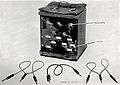
Front view
Rear view
_1932_-_Plate_3.jpg)
_1932_-_Plate_4.jpg)
Related Pages
- No related pages at this time
Related Items
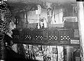
Buzzer Switches 4+3 in dugout
